upcoming conferences
PCIM Europe 2024
Booth: 9-518
Location:
Nuremberg, Germany
Dates:
June 11-13, 2024
Latest news
Advanced Conversion Designs High Performing DC Link Capacitor with Cissoid SA
Advanced Conversion is excited to announce our collaboration with Cissoid SA, headquarters in Belgium, via [...]
Read MoreAdvanced Conversion is upgrading to AS91000 Standard – Quality Management Systems – Requirements for Aviation, Space and Defense
Advanced Conversion, a wholly owned subsidiary of Electro Technik Industries (ETI) announced that it has [...]
Read MoreAdvanced Conversion Colorado Expands Its Facility
Loveland, CO August 2, 2023 – For immediate release Advanced Conversion is very pleased to [...]
Read More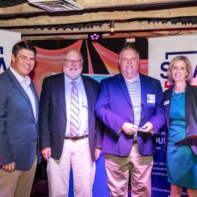
Advanced Conversion Named 2023 Vermont Exporting Business of the Year
Advanced Conversion was named 2023 Vermont Exporting Business of the Year by the U.S. Small [...]
Read More
21
Jun
Jun